Sonntag, 22. Oktober 2017

Verkabelung

Nach dem Fertigstellen der Motorverkabelung konnte ich für die restlichen Kabel auf das mit dem Bausatz gelieferte Material zurückgreifen.
Da ich allerdings eine völlig andere Instrumentierung, Funkausrüstung, Autopilot usw. verwende ist ein erheblicher Teil des Kabelbaums übrig geblieben.


Durch die farbcodierten Kabel mit teilweise vormontierten Steckern war das korrekte Anschließen leicht zu bewerkstelligen.

Im Bereich der Flügelwurzel wurden Stecker zur Versorgung von Landescheinwerfer, Positionslicht usw. montiert.


Stecker im Rumpf mit Abdeckung

Gegenstecker im Flügel

Hinter dem Instrumenten Paneel wurde es immer enger und chaotischer.
Nachdem alles fertig angeschlossen und ausgetestet war, habe ich noch versucht durch Verwendung von Spiral.- und Faltenschläuchen das Erscheinungsbild zu verbessern.

Instrumentenabteil in Arbeit
Fertiges Instrumentenabteil

Die Gummitüllen für die Kabeldurchführungen im Brandspant wurden mit speziellen Blechen abgedeckt und mit hitzebeständigem Silikon eingedichtet.


Abdichtung Kabel-Brandspant

Nach der Montage des Abdeckblechs über dem Instrumentenabteil wurde nochmals alle Systeme überprüft. Alles funktioniert wie geplant. 😁👍


Sonntag, 30. Juli 2017

Rotax 912 iS Engine Cabling


Rotax 912 iS Engine Cabling

The sensors and actuators of the 912iS engine are fitted at factory and connected to the engine wiring harness.
The builder/installer needs to connect the harness to:
- ECU (Control unit)
- FUSE BOX
- Cockpit (switch, instruments, maintenance connection)

The wiring harness consists mainly of two cable looms.  To rout this quite stiff and long cable looms through the fire wall within the limited space in the RV12  took me some effort.
Wiring harness
Fire wall penetration
The main effort are the two HIC (Harness Interface Connectors) which connects the control and monitoring instruments and maintenance ports to the engine.
Following a tip from Rotax I acquired prefabricated cables with the HIC connectors already on.

Connectors as supplied by Rotax
I sent the connectors to a little local company (MLT Maschinen Leitungstechnik GmbH, http://www.mlt.at/ ) 
In return I received cabling of adequate length and size with the HIC connectors on one end. 
Each wire correct labeled. But I intend to replace the yellow slip on labels by heat shrink typ.

HIC connectors in place

Having one side of the connections already done saved me a lot of time.
But to connect the countless number of wires to the different locations including a few d-sub connectors was a tedious work for me. 😅

Engine cabling finished
One of the five DA20 Katana of our flying club Weiße Möwe Wels (http://www.wmw.at/) has been equipped with a 912iS engine recently.
I did the electrical installation exactly the same way as worked out for this airplan by rotax employee.
This includes the EMU (Engine Management Unit) from Stock Flight Systems. www.stockflightsystems.com
To follow this tried and proven path turned out to be a wise decision when I turned on the system for the first time.
A little error I made was corrected quickly. I have had connected a few ground wires to regulator B instead of regulator A.
As soon as I hooked up this wires correctly everthing worked as expected. 😀😂

EMU alive
I hope this success will continue at the day of the first engine start. Fingers crossed!


Sonntag, 12. März 2017

Bau der Flügel


Während der lezten 10 Monate habe ich immer zwischendurch am Flügel gearbeitet.
Immer dann wenn ich für den Motoreinbau auf irgendwas warten musste oder einfach eine Nachdenkpause notwendig war, wurden wieder ein paar Arbeitsschritte erledigt.
Wie im Post "Vorbereitung für den Bau der Flügel" beschrieben, waren die Flaperons und Hilfsholme schon seit längerem fertig.
Das Entgraten und Richten (fluten) der Rippen hat sich als sehr mühsam und zeitaufwändig erwiesen.

Rippen vor und nach dem Richten
Bevor mit dem Aufbau des Flügels begonnen werden konnte mussten die meisten Rippen für die jeweilige Einbauposition zurechtgetrimmt und einige Annietmuttern befestigt werden.
Einige der fertigen Rippen
Der Aufbau der Flügelstruktur und das Beplanken mit den vorgebohrten und gebogenen Blechen war dann schnell erledigt.
Zuerst wurden am Flügelholm Befestigungswinkel für die Rippen angenietet.
Flügelholm

Rippen mit hinterem Hilfsholm

Flügelstruktur mit eingezogenen Kabeln

Nieten der unteren Beplankung

Fertig für die obere Beplankung

In die Vorderkante des linken Flügels wurde noch die Überziehwarnung eingebaut.
Schalter für die Überziehwarnung
Im rechten Flügel ist der Landescheinwerfer positioniert.

Landescheinwerfer

Fertig genietet 

Randbogen

Mittwoch, 30. November 2016

ROTAX 912 iS Installation

The installation of a Rotax 912 iS fuel injected engine in a Vans RV12 appears to be of interest for many people throughout the aviation world. So I decided to write all engine related postings in English language.

Last summer I ordered the engine for my Vans RV12. The decision to use the new fuel injected engine had already been made before I placed the order to Vans Aircraft. Since then I have had many long discussions to some fellow pilots. As a result I got convinced that a constant speed propeller will further enhance the performance of the RV12. I am not focused to top or high cruising speed but I like good climb performance (important in the Austrian Alps) and endurance.
The downside is the additional weight and forward shift of CG.
I had the opportunity to analyse the weight&balance data OE-ATT of fellow RV12 builder Toni.
My conclusion was: 5 kg (11 lbs) more weight of the Engine will shift the CG forward by approximately 12mm (1/2 in). Some of the equipment like fuel pumps, gascolator, etc. can be located in the back and will compensate some of the extra weight in the front.
I'm convinced it is possible to handle the additional weight of fuel injection and constant speed propeller satisfactorily.
Early August I picked up the engine at the near by Rotax Dealer HB Flugtechnik www.hb-flugtechnik.at

Rotax 912 iS Sport S3 still in the box
Rotax delivers the engine including engine ring mount. This engine mount does not fit to the RV12 firewall and needs to be replaced by the Vans mount.
Doing this required some modifications.
This was no surprise. Before I ordered the RV12 kit a friend made a CAD analysis for me. This showed clearly  what I experienced now in reality.

1. Coolant pump: one hose interferes with the engine mount.

Vans ring mount - unmodified coolant pump
     It was an easy task to turn the fitting of the coolant pump to the required position.

Modified coolant pump reinstalled


2. Exhaust system:
The clearance between muffler and engine mount was just 1mm.

Vans ring mount - Rotax exhaust
The relocation of the muffler required some more effort as the coolant pump.
I had to cut all four exhaust pipes and to extend the rear ones by additional ball joints.
It took some time to tack weld everything in the correct position and to get it welded by a qualified welder.

Modified exhaust
Having today's experience  I would choose the exhaust system as supplied by Vans Aircraft.
Welding in the four little nozzles for the exhaust temperature probes appears much easier and cheaper than the relocation of the muffler. Furthermore the position of the temperature probes could be optimized.

Temperature probe touching the cooling shroud
After reinstallation of coolant pump and exhaust it was a quick job to hang the engine to the firewall.


Fuse Box:
Finding a good location for the fuse box  caused me some headache.
Finally I got the tip to take one of the regulators off and to install it nearby.
I took regulator B off and positioning the fuse box was much easier
Now I have good access to the front cover as well as to the three connectors.

Fuse box installed

ECU (Engine Control Unit):
The ECU can't be placed in the engine compartment. It must be installed in the cockpit.
The top of the Map Box is a perfect place for the ECU.

ECU mounted on Map Box
Oil tank:
The oil tank was almost in front of the throttle body.
It appeared very difficult to position an air filter and to prevent the air hose from rubbing and wearing on the oil tank flange or filler cap.

Oil tank in original position
I decided to lower the oil tank to the position recommended by Rotax.
The oil  in the tank should be at the same level as the oil pump.

Oil tank in lower position
This was a good opportunity to modify the battery mount to accept a Lithium battery.
The weight saving is at least 5 kg (11 lbs). 😀

Coolant hoses:
The slightly different location of the expansion tank on the 912 iS engine requires a modified routing of the coolant hose on top of the engine.
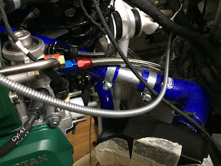
Coolant hose upstream cooler
The hose downstream the cooler was routed as direct as possible to the pump. This keeps the left side free for the fuel system (Fine filter, bypass orifice and pressure sensor)

Coolant hose downstream cooler

Oil hoses:
It took me several attemps to figure out the best configuration of the oil hoses. 
My intention was to do it the same way as planned for the caburated engine.
There is a significant difference between the Vans and the Rotax exhaust system which I use.
The exhaust pipe of cylinder 1 is just in front of the oil pump. This does not allow a straight in connection. A 45° fitting on the pump solved that problem.

First attempt: 
Similar to the caburated engine. The hose from oil tank to the cooler runs at the back of the engine to the left side and underneath the cylinders forward to the cooler. To fix that hose in a good way to avoid rubbing and wearing on sensitive parts like speed sensors appeared very difficult.
The bending radius of the hose from cooler to oil pump was very small. 
Due to the stiffness of the used teflon hoses the cooler was pushed out of position. The installation of the lower cowling was a real challenge. 
I decided to look for a better configuration.
First attempt
Secound attempt:
The hose from the oiltank runs down on the right hand side to the cooler. The hose on the cooler outlet (left side) runs in front of the oil pump and is conneced to the pump via a 180° fitting. 
Second attempt
After installation of the cowling the glass fibre air duct to the radiator was pushing up the hose to the oil pump. The clearance to the oil filter became minimal. 
There must be somthing better! 😓

Third attempt:
Increased the length of the hose from tank to cooler. The connection on the cooler is now a 150° fitting.
The hose from cooler to oil pump runs behind the cooler (but with enough clearance to the muffler) to the right side and connects to the pump via the 45° fitting. 😃

Final configuration of oil hoses


Montag, 17. Oktober 2016

Canopy

Die Kabinenhaube besteht im wesentlichen aus einem Alurahmen und der Haube aus Plexiglas.
Bei Arbeiten mit Plexiglas besteht immer die Gefahr, Risse zu bekommen. Um diese Gefahr möglichst zu minimieren, habe ich versucht, die kritischen Phasen in den heißesten Tagen dieses Sommers zu erledigen. Je höher die Temperatur, desto zäher und weniger rissanfällig ist das Material.

Leider war der Rahmen stark verzogen und musste mühsam gerichtet werden. Das war vermutlich auch eine Folge der groben Behandlung der Kisten beim Transport.

Seitlicher Versatz ca. 15mm
Der Bügel des Rahmens sollte parallel zum Überrollbügel stehen

Nach fast einer Woche herumbiegen und richten waren meine Qualitätsansprüche erreicht,
bzw. meine Geduld am Ende.

Der Rahmen passt

Eine erste Sitzprobe

Die Haube musste an allen Rändern mit einer kleinen Trennscheibe zurecht geschnitten werden.


Nachdem alles passte, und die Ränder sauber verschliffen waren, wurden die Niet- bzw. Schraubenlöcher durch das Plexiglas in das Alu gebohrt.


Alle Löcher mussten noch sauber entgratet werden, dann konnte die Haube mit den seitlichen Abschlussblechen an den Rahmen geheftet werden.


Fertig zum Nieten und Verschrauben
Die Gasdruckfedern halten die Haube offen

Das Vernieten mit dem vorderen Rahmen konnte ohne Riss in der Haube abgeschlossen werden. Nach der Montage der Gasdruckfedern lässt sich die Haube leicht öffnen und schließen.
Alles passt zufriedenstellend!

Um die weiteren Arbeiten wie Einbau von Motor, Instrumentierung und Verkabelung nicht zu behindern, habe ich die Haube wieder abgebaut und sicher verwahrt. 
Sie wird erst wieder nächsten Frühling zur Endmontage des ganzen Flugzeugs hervorgeholt werden.