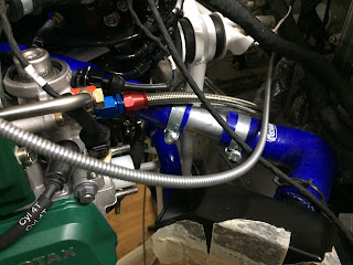
Last summer I ordered the engine for my Vans RV12. The decision to use the new fuel injected engine had already been made before I placed the order to Vans Aircraft. Since then I have had many long discussions to some fellow pilots. As a result I got convinced that a constant speed propeller will further enhance the performance of the RV12. I am not focused to top or high cruising speed but I like good climb performance (important in the Austrian Alps) and endurance.
The downside is the additional weight and forward shift of CG.
I had the opportunity to analyse the weight&balance data OE-ATT of fellow RV12 builder Toni.
My conclusion was: 5 kg (11 lbs) more weight of the Engine will shift the CG forward by approximately 12mm (1/2 in). Some of the equipment like fuel pumps, gascolator, etc. can be located in the back and will compensate some of the extra weight in the front.
I'm convinced it is possible to handle the additional weight of fuel injection and constant speed propeller satisfactorily.
Early August I picked up the engine at the near by Rotax Dealer HB Flugtechnik www.hb-flugtechnik.at
 |
| Rotax 912 iS Sport S3 still in the box |
Doing this required some modifications.
This was no surprise. Before I ordered the RV12 kit a friend made a CAD analysis for me. This showed clearly what I experienced now in reality.
1. Coolant pump: one hose interferes with the engine mount.
 |
| Vans ring mount - unmodified coolant pump |
 |
| Modified coolant pump reinstalled |
2. Exhaust system:
The clearance between muffler and engine mount was just 1mm.
 |
| Vans ring mount - Rotax exhaust |
I had to cut all four exhaust pipes and to extend the rear ones by additional ball joints.
It took some time to tack weld everything in the correct position and to get it welded by a qualified welder.
 |
| Modified exhaust |
Welding in the four little nozzles for the exhaust temperature probes appears much easier and cheaper than the relocation of the muffler. Furthermore the position of the temperature probes could be optimized.
 |
| Temperature probe touching the cooling shroud |
Fuse Box:
Finding a good location for the fuse box caused me some headache.
Finally I got the tip to take one of the regulators off and to install it nearby.
I took regulator B off and positioning the fuse box was much easier
Now I have good access to the front cover as well as to the three connectors.
 |
| Fuse box installed |
ECU (Engine Control Unit):
The ECU can't be placed in the engine compartment. It must be installed in the cockpit.
The top of the Map Box is a perfect place for the ECU.
 |
| ECU mounted on Map Box |
The oil tank was almost in front of the throttle body.
It appeared very difficult to position an air filter and to prevent the air hose from rubbing and wearing on the oil tank flange or filler cap.
 |
| Oil tank in original position |
The oil in the tank should be at the same level as the oil pump.
 |
| Oil tank in lower position |
The weight saving is at least 5 kg (11 lbs). 😀
Coolant hoses:
The slightly different location of the expansion tank on the 912 iS engine requires a modified routing of the coolant hose on top of the engine.
 |
| Coolant hose upstream cooler |
The hose downstream the cooler was routed as direct as possible to the pump. This keeps the left side free for the fuel system (Fine filter, bypass orifice and pressure sensor)
 |
| Coolant hose downstream cooler |
Oil hoses:
It took me several attemps to figure out the best configuration of the oil hoses.
My intention was to do it the same way as planned for the caburated engine.
There is a significant difference between the Vans and the Rotax exhaust system which I use.
The exhaust pipe of cylinder 1 is just in front of the oil pump. This does not allow a straight in connection. A 45° fitting on the pump solved that problem.
First attempt:
Similar to the caburated engine. The hose from oil tank to the cooler runs at the back of the engine to the left side and underneath the cylinders forward to the cooler. To fix that hose in a good way to avoid rubbing and wearing on sensitive parts like speed sensors appeared very difficult.
The bending radius of the hose from cooler to oil pump was very small.
Due to the stiffness of the used teflon hoses the cooler was pushed out of position. The installation of the lower cowling was a real challenge.
I decided to look for a better configuration.
 |
| First attempt |
Secound attempt:
The hose from the oiltank runs down on the right hand side to the cooler. The hose on the cooler outlet (left side) runs in front of the oil pump and is conneced to the pump via a 180° fitting.
 |
| Second attempt |
After installation of the cowling the glass fibre air duct to the radiator was pushing up the hose to the oil pump. The clearance to the oil filter became minimal.
There must be somthing better! 😓
Third attempt:
Increased the length of the hose from tank to cooler. The connection on the cooler is now a 150° fitting.
The hose from cooler to oil pump runs behind the cooler (but with enough clearance to the muffler) to the right side and connects to the pump via the 45° fitting. 😃
 |
| Final configuration of oil hoses |
